
I don’t need to. I’ve owned it for about 5 years, I know it’s fine. The next run will be when I have time.
Aww good to see her back! 
Lol, why do you guys keep trying to personify it? 
1 Like
Lol. Just for fun…
1 Like
 Great job - she looks like going for a walk
… and btw this yellow sky/sun thing from the other day seemed to be caused by sahara desert ( just one „s“  ) sand- blown up in the atmosphere somehow- heard it on the radio rn
2 Likes
Camazotz fried yet another circuit board yesterday. For some reason it really pissed me off; probably because I spent ages trying to fix it. I’ll buy one last board and replace / upgrade the MOSFETs before they get fried this time. If they burn out again, I don’t know what I’ll do with it. I’ll probably forget about it as a project. 
1 Like
You’re very skilled and can fix everything! I have trust in you!  if you fail this time it doesn’t matter!it’s another experience to add to your knoledge in this subject…
  stay strong!
1 Like
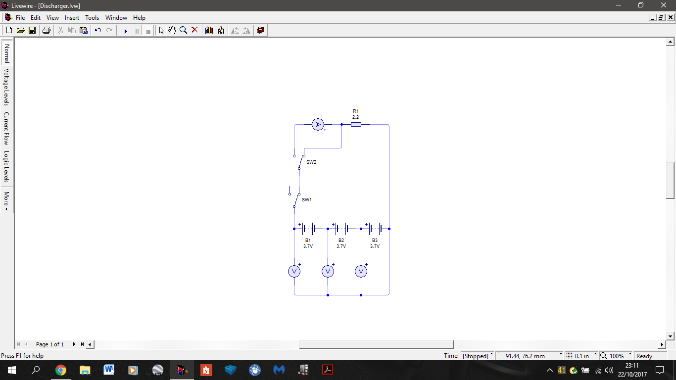
I just designed a dead simple battery discharger for my batteries because my charger didn’t actually come with a built in discharger. You’d think a £45 charger would come with a discharger too but no.
Anyway, this will discharge my batteries through a 2.2 Ohm load resistor. Theoretically my 3S should discharge at 5.05A and my little 1S batteries that I use for Camazotz will be wired as 2S batteries and will discharge at 3.36A. So all should be fine, not damaging the batteries at all and hopefully not generating too much heat. The 3 voltmeters in the diagram represent one of those little compact ones that read all of your cells. The design also has an ammeter bypass for when I don’t need and / or want to hook up my ammeter.
To be honest I wouldn’t even have to design this if my projects are more reliable  . They usually break before the battery gets below 50% and then my proper charger refuses to store charge them. Hopefully I can get this built in the next week or so if I have time.
2 Likes
That a really good idea i hope it goes good
For u .
1 Like

Sit rep: I bought all of the components for the discharger and the PCB for Camazotz. Hopefully they’ll come soon.
2 Likes
whats that??
The micro RC project.
you mean more smaller RC ? For building discharger?
I’m building the discharger in general for all of them, but yes, the smaller one. It’s all in the OP.
1 Like
Most of my parts came in today, just waiting for 2 or 3 things more to come.
1 Like
Oh nice… you mean that small RC came today? Can i see it?
No, you’re misunderstanding me. Project Camazotz is the small one. I’m not getting a 4th RC. I just ordered another circuit board because I fried the one it has for the second time.
Oh… i got it  actually this confused me a bit…
Yeah looking forward for the progress updates
Sit rep: I’m an idiot
Yesterday I realised that I didn’t think to calculate for the power dissipation of the load resistor. Luckily I recalculated and bought the correct value. I initially had a 0.25W , 2.2 Ohm load resistor. What I didn’t realise was what sort of power dissipation would result from that resistor value and my battery voltage. With 2.2 Ohms I was looking at 72W for a 3S lipo at max voltage. That’s 288 times more than the resistor can handle.
Luckily I recalculated and bought the appropriate resistor. The calculations are easy. If for some reason you’re interested in the calculations they are below (I’ve explained the key steps).
Calculations
The calculations are really nothing complicated at all, just use of Ohm’s law and electrical power equations.
NOTE: Anywhere I say 2S lipo I actually mean my small 1 cell lipos wired together so that I can do 2 at once.
Ohm's law
V = I x R or I = V / R or R = V / I
Where , V= Voltage in Volts, I = Current in Amps, R= Resistance in Ohms.
Electrical power equations
P = I x V
P = I^2 x R
P = (V^2) / R
Where P = Power in Watts.
These can obviously be rearranged.
Since I designed the discharger to discharge my batteries to just below 50% capacity I didn’t have to account for the battery voltage below the nominal voltage of 3.7V /cell as at about 50% capacity that’s the rough voltage of the cells.
Calculating initial power dissipation:
When it first dawned on me that my initial resistor (2.2 Ohms , 0.25W) might not be enough I started to calculate the power dissipation for the nominal and maximum voltages of my 2S and 3S LiPos (7.4V / 8.4V and 11.1V / 12.6V respectively).
I started with the max for my 3S which is 12.6V and we know R = 2.2 Ohms.
Therefore I use P = (V^2) / R
P 3S Max = (12.6^2) / 2.2
P 3S Max = 72W This is 288 times more than the 0.25W resistor can handle.
For the power dissipation of the other voltages the calculation is the same so below are only the final answers.
P 3S Nom = 56W
P 2S Max = 32W
P 2S Nom = 25W
As you can see all of these value are way too high for the resistor to be able to handle. At this point I took to ebay to see what the highest power resistor was for a reasonable price. The highest value I found was 50W. This is lower than the P 3S values, that meant that in order to lower the power I either had to lower the voltage (which in this case isn’t really possible) or the current.
Now as we know from Ohm’s law, in order to lower the current we have to increase the resistance. Of course I didn’t want to lower the current too much because the lower the current, the slower the battery will discharge. We know that 2.2 Ohms is too low so I had to look for a higher value. At this point it’s a bit of trial and error with what value you go for. I went for 3.3 Ohms first and it turned out to be a good selection.
Calculation of new discharge current:
Notice here how I am not using the power equations for the current. Using the power equations will give me current at max power. This is not what I want as power is dependent on voltage, current and resistance not vice versa. The power rating is the max it can dissipate NOT how much it will dissipate regardless of the voltage across it, current through it or its resistance.
So here I’m using I = V / R to calculate the current through the new 3.3 Ohm resistor at same voltages as before. Again I will only do the working for 1 value and just give answers for the rest.
I 3S Max = 12.6 / 3.3
I 3S Max = 3.8A
I 3S Nom = 3.4A
I 2S Max = 2.5A
I 2S Nom = 2.2A
Now I just substitute these values into P = I x V to get my final power dissipation.
P 3S Max = 3.8 x 12.6
P 3S Max = 48W
P 3S Nom = 38W
P 2S Max = 21W
P 2S Nom = 16W
Now you can see that all the values are below 50W so the resistor can handle them. The next step is calculating the discharge C rate at those current values.
Note: If you do not know what C is go to the glossary in the OP of this thread
Calculating discharge C rate:
This stage is to see if the discharge current will be too big for the batteries to handle. This step is more for the sake of the 2S lipo as these sorts of currents are child’s play for the 3S.
My 2S is 600 mAh (0.6 Ah) and is rated for 35C , so it’s max continuous discharge current is:
0.6 x 35 = 21A
You can see that that is way more than we will be drawing. It is in fact only 4.2C. Below are the C values for the final current values.
C 3S Max = 0.7C
C 3S Nom = 0.6C
C 2S Max = 4.2C
C 2S Nom = 3.6C
Calculating discharge time at given C rating:
This stage isn’t really necessary but I calculated how long it would take roughly to discharge the batteries halfway. I just used an online calculator for this. The results are as follows:
Discharge from V 3S Max to just below V 3S Nom = 48 mins
Discharge from V 2S Max to just below V 2S Nom = 4 mins
On another note I found a pic on my phone of possibly the worst RC car I’ve ever had. I don’t know anything about it other than that it uses slot car motors to get around and steer. It was pathetically slow (~ 1.5 mph) and terrible in every way.

3 Likes