
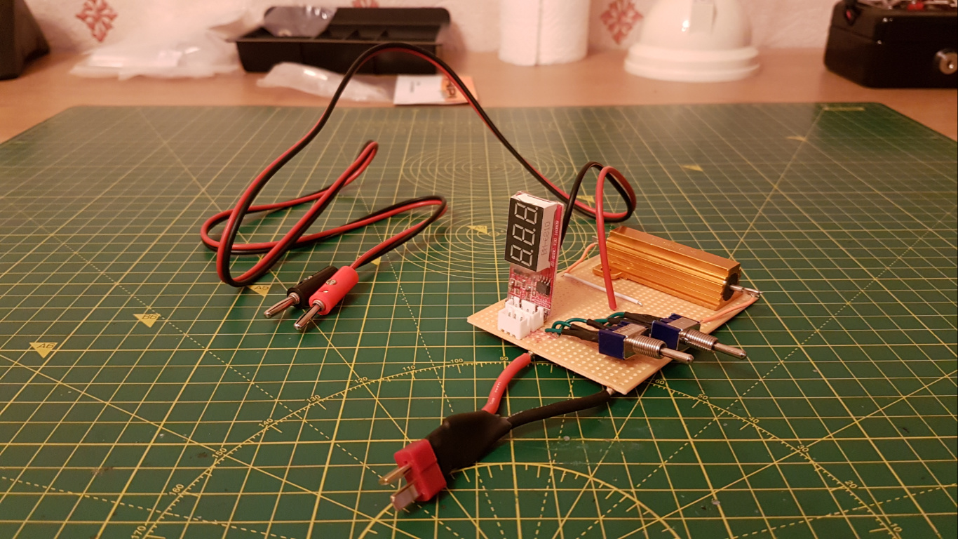
Decided to build the dischrager earlier this evening. It looks pretty shoddy. I might add another plug for 1S discharge for when the 1 cells in the 2S pairing are mismatched in voltage from Camazotz. I need to stick the switches and resistor to the board too.
5 Likes
It looks like u are doing a good job
1 Like
Meh, it’s mediocre at best. I just need it to work.
I actually have no idea what you’re building here 
I don’t understand the function of a discharger. (Can you tell I’m not into engineering?  )
)
1 Like
Lol, sorry. A discharger is the opposite of a charger. Instead of ‘filling’ your batteries with electricity it empties them.
My proper battery charger doesn’t have a discharge function. And if the batteries are above 50% full the charger refuses to charge them for storage; it can only charge them to 100% if they are above 50% as it has no way to bring them down. Lithium batteries need to be kept at about 50% full when they’re not in use for over 3 or 4 days.
So I built this discharger to drop the batteries to below 50% so that my proper charger can charge them for storage.
1 Like
Oh even i didn’t knew about it properly! 
I thought the name was clear enough. 
If you’re not here from the OP you can ignore this post.
Note : PLEASE DO NOT EDIT THIS POST, IT IS ONLY A WIKI SO THAT THE EDIT TIME DOESN’T EXPIRE.
I decided to design a simple discharger because my charger didn’t come in with a built in discharger. This meant that if my batteries were above 50% full it would not store charge them. The purpose of the discharger is to discharge them to just below 50% so that my charger can then store them.
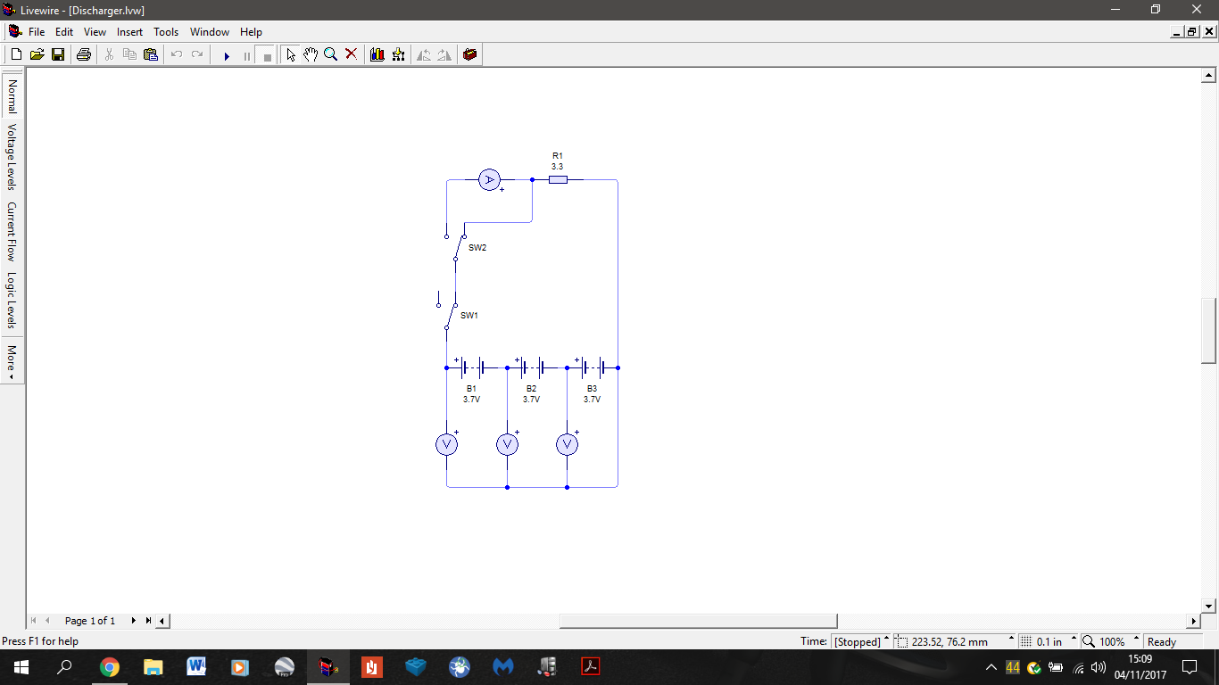
The design is very simple, I’m just discharging the batteries through a load resistor. I have included a mini voltmeter to monitor the cell voltages and have made a plug-in terminal for my multimeter so I can monitor the discharge current. I have also included an multimeter bypass for when I’m too lazy to take it out or for when I don’t need it as I know the battery’s behaviour. I soldered the circuit onto a stripboard because I don’t have the facilities to make a PCB.
Initially I made the mistake of not calculating the power dissipation of the resistor and was planning on using a 2.2 Ohm , 0.25W resistor. Luckily I decided to go back and do the calculations before I actually built and tested it with the 0.25W resistor. I calculated that with a 2.2 Ohm resistor I’d be dissipating ~72W. So I recalculated and got a 3.3 Ohm, 50W resistor instead. All calculations are below.
Calculations
The calculations are really nothing complicated at all, just use of Ohm’s law and electrical power equations.
NOTE: Anywhere I say 2S lipo I actually mean my small 1 cell lipos wired together so that I can do 2 at once.
Ohm's law
V = I x R or I = V / R or R = V / I
Where , V= Voltage in Volts, I = Current in Amps, R= Resistance in Ohms.
Electrical power equations
P = I x V
P = I^2 x R
P = (V^2) / R
Where P = Power in Watts.
These can obviously be rearranged.
Since I designed the discharger to discharge my batteries to just below 50% capacity I didn’t have to account for the battery voltage below the nominal voltage of 3.7V /cell as at about 50% capacity that’s the rough voltage of the cells.
Calculating initial power dissipation:
When it first dawned on me that my initial resistor (2.2 Ohms , 0.25W) might not be enough I started to calculate the power dissipation for the nominal and maximum voltages of my 2S and 3S LiPos (7.4V / 8.4V and 11.1V / 12.6V respectively).
I started with the max for my 3S which is 12.6V and we know R = 2.2 Ohms.
Therefore I use P = (V^2) / R
P 3S Max = (12.6^2) / 2.2
P 3S Max = 72W This is 288 times more than the 0.25W resistor can handle.
For the power dissipation of the other voltages the calculation is the same so below are only the final answers.
P 3S Nom = 56W
P 2S Max = 32W
P 2S Nom = 25W
As you can see all of these value are way too high for the resistor to be able to handle. At this point I took to ebay to see what the highest power resistor was for a reasonable price. The highest value I found was 50W. This is lower than the P 3S values, that meant that in order to lower the power I either had to lower the voltage (which in this case isn’t really possible) or the current.
Now as we know from Ohm’s law, in order to lower the current we have to increase the resistance. Of course I didn’t want to lower the current too much because the lower the current, the slower the battery will discharge. We know that 2.2 Ohms is too low so I had to look for a higher value. At this point it’s a bit of trial and error with what value you go for. I went for 3.3 Ohms first and it turned out to be a good selection.
Calculation of new discharge current:
Notice here how I am not using the power equations for the current. Using the power equations will give me current at max power. This is not what I want as power is dependent on voltage, current and resistance not vice versa. The power rating is the max it can dissipate NOT how much it will dissipate regardless of the voltage across it, current through it or its resistance.
So here I’m using I = V / R to calculate the current through the new 3.3 Ohm resistor at same voltages as before. Again I will only do the working for 1 value and just give answers for the rest.
I 3S Max = 12.6 / 3.3
I 3S Max = 3.8A
I 3S Nom = 3.4A
I 2S Max = 2.5A
I 2S Nom = 2.2A
Now I just substitute these values into P = I x V to get my final power dissipation.
P 3S Max = 3.8 x 12.6
P 3S Max = 48W
P 3S Nom = 38W
P 2S Max = 21W
P 2S Nom = 16W
Now you can see that all the values are below 50W so the resistor can handle them. The next step is calculating the discharge C rate at those current values.
Note: If you do not know what C is go to the glossary in the OP of this thread
Calculating discharge C rate:
This stage is to see if the discharge current will be too big for the batteries to handle. This step is more for the sake of the 2S lipo as these sorts of currents are child’s play for the 3S.
My 2S is 600 mAh (0.6 Ah) and is rated for 35C , so it’s max continuous discharge current is:
0.6 x 35 = 21A
You can see that that is way more than we will be drawing. It is in fact only 4.2C. Below are the C values for the final current values.
C 3S Max = 0.7C
C 3S Nom = 0.6C
C 2S Max = 4.2C
C 2S Nom = 3.6C
Calculating discharge time at given C rating:
This stage isn’t really necessary but I calculated how long it would take roughly to discharge the batteries halfway. I just used an online calculator for this. The results are as follows:
Discharge from V 3S Max to just below V 3S Nom = 48 mins
Discharge from V 2S Max to just below V 2S Nom = 4 mins
Here are pics of the circuit diagram and the final build. The 3 voltmeters in the diagram represent the small one that measures the cells.
Oh now I see… kinda
That reminds me of Engineering class. We had to draw those circuit diagrams on our tests
It basically empties the battery. If you like you can look at it as if it is tricking the battery into thinking that it is powering an RC car.
1 Like
I’m adding a basic electronics section to the OP glossary. However, it makes the OP exceed the character limit so I’m linking this post to the OP. This might help some of you out. Also it likely has typos and grammar errors I missed so if you find one please tell me.
Note : PLEASE DO NOT EDIT THIS POST, IT IS ONLY A WIKI SO THAT THE EDIT TIME DOESN’T EXPIRE.
-Current: The flow of electrons in a circuit. Measured in Amps (A), represented as I in equations.
-Voltage: The ‘force’ pushing the electric current in a circuit, measured in Volts (V), represented as V in equations.
-Resistance: How easily a conductive material will allow a current to flow through it. Measured in Ohms (Ω), represented as R in equations.
-Power: Usually defined as energy over time. Measured in Watts (W), represented as P in equations. But electrical power is dependent on voltage, current and resistance. Equations for finding power are as follows. P = I x V or P = (V^2) / R or P = I^2 x R
-Ohm’s law: A set of equations that allow you to calculate voltage or current or resistance give one unknown, if there are 2 or more unknowns then they cannot be used. The equations for Ohm’s law are as follows. V = I x R and I = V / R and R = V / I Of course to find voltage, current and resistance you can also manipulate the previous power equations.
-Multimeter: A piece of equipment that can take measurements on physical circuits of current, voltage, resistance and other such parameters. If the device can only measure voltage it is called a voltmeter or if it only measures current then it is called an ammeter , people often use the terms interchangeably (and sometimes incorrectly).
Load resistance: Any resistance in the circuit that draws power. For example in a simple circuit of a battery, a switch and a light bulb, the light bulb is the load resistance. Sometimes only referred to as just the load. Also often when somebody says the load, they mean the main load of the circuit as there are bound to be many loads. For example in a stereo system the main loads are the speakers regardless of other components in the amplifier or CD player.
-AC: Stands for alternating current, is a form of electricity and is represented as a sine wave as AC oscillates between positive and negative voltage. Mains electricity is AC. AC is far more dangerous than DC for reasons too long to explain in a glossary.
-DC: Stands for direct current and is the other form of electricity. On a graph it is just a horizontal line as it is only a positive voltage or only a negative and does not have a frequency. DC is less dangerous than AC. A battery provides DC voltage. Most home appliances run on DC, despite mains being AC. AC to DC conversion is done with a bridge rectifier.
-Cycle: When a sine wave goes from zero to its positive peak, back down to zero, then to its negative peak and back to zero.
-Period: The time for one cycle, usually denoted by T. Time is a lowercase t , period is a capital T.
-Frequency: The amount of cycles per second of a signal. Measured in Hertz (Hz), represented as f in equations.
-Amplitude: The distance between zero and the top of a peak of a sine wave.
-Amplifier: It’s in the name, it’s a device that amplifies a signal. So if the input signal has a 10V amplitude and the amplifier had a gain of 10 (gain has no units) the output voltage would be 100V (because 10V x 10 gain). Gain that is 1 means no gain as there is no change. Below 1 means the signal is being attenuated, above 1 means it is getting amplified.
-Attenuator: The exact opposite of an amplifier, it takes a signal and lowers its amplitude. So the 10V from above would go to 1V if the attenuator had a gain of 0.1.
-Resistor: A circuit component with a specific resistance. One of the most widely used components in electronics, they allow you to control the voltage and current characteristics of your circuits. They dissipate energy as heat.
-Diode: A component that lets current flow in one direction. Most diodes are made of silicone and have a minimum activation voltage of 0.7V.
-LED: Stands for Light Emitting Diode, it is literally a diode that glows when electricity is passed through it.
-Capacitor: A component that temporarily stores electric charge and sheds it very rapidly (almost instantly). Often used in camera flashes and defibrillators (that whining noise is the capacitor charging) as well as a lot of other places. If a circuit goes pop, then it’s most likely a capacitor blowing up.
-Breadboard / Prototype board: A type of circuit board with a specific arrangement of track columns and rows. Used solely for the purpose of testing a circuit before soldering it as you can place and remove components freely and as you please. It’s like Lego but with circuit components.
-Strip board / Vero board: A permanent type of circuit board with a distinct layout of tracks in columns and holes for components. One side is coated in copper and the other isn’t. Soldering is done on the conductive copper side.
-PCB: Stands for Printed Circuit Board, it is the only type of board used in real electronics that you buy as it allows for a completely custom design in terms of component and track placement. This allows for very compact circuit boards. Making a PCB requires special equipment, that’s why most hobbyists use strip boards if they don’t have the equipment to make PCBs.
-THT: Stands for Through Hole Technology. It refers to components with legs that go through the circuit board and need to be soldered, they are often big and bulky and aren’t used in compact electronics.
-SMT / SMD: Stands for Surface Mount Technology or Surface Mount Device(s). The other type of components. These do not need to go through the circuit board but are stuck on with special conductive paste. These components can be absolutely tiny. Your mobile phone has thousands of them.
-Soldering: The process of attaching components to a circuit using a soldering iron and solder.
-Soldering iron: A piece of equipment (usually electrically powered) that looks like a big pen. It has a very hot metal tip (usually 300 - 450 degrees Celsius) that melts solder so that you can attach components to circuit boards.
-Solder: A specific blend of metals that has a specific melting point. It comes in reels and looks like a wire but is softer and breaks easily. It is melted by the soldering iron and applied to the components’ legs or pins to hold them to the circuit. In other words you are melting metal and using it as glue to hold components. Solder solidifies in 1-2 seconds once melted. Solder is electrically conductive.
3 Likes
Oh crap, that’s like an entire dictionary
Edit: read it  . Again this is reminiscent of my engineering classes. I actually remember most of it
1 Like
This isn’t even the tip of the iceberg
Lol I know, but talking about the average length of forum posts, this is huge
Yeah, the RC glossary was pretty long too.
Very cleanly done, a semester of physics/elect engr in a 5min read lol
1 Like
Sort of lol. Closer to being able to avoid high school level circuit theory in physics.
Aye so nice! Shortened electric basic summary. Clearly mentioned important stuffs 
1 Like